UVMapping with Wings for Dummies, v. 0.1

UVMapping with Wings for Dummies, v. 0.1

Share and discuss visual creations and creation practices like texturing, modelling and musing on the meaning of life.

Moderators: MR.D, Moderators

User avatar
Argh
Posts: 10920
Joined: 21 Feb 2005, 03:38

UVMapping with Wings for Dummies, v. 0.1

Post by Argh »

Hey folks. I'm going to write a tutorial about how to uvmap using Wings, now that I am familiar with it. It took me about 2 hours to decipher the interface and figure this out, but I'm sure that since many of you folks are using Wings, or need a freeware uvmapping solution, this will be very helpful.

Also, since Wings can unfold very complex things (if you know how to give it hints properly) I figured that this will help everybody- many projects want to work with complex organic curvature that may not be easily-mapped otherwise.

So, let's begin.

First off, you're going to need this irregular shape that I'm providing. This was made in Rhino3D 3.0, and it works perfectly in Wings after welding it completely together (Rhino users, this means meshing it, triangulating it, and then selecting the object and using Weld with a 179-degree tolerance).

I selected an irregular (but not too weird) shape, because uvmapping a cube doesn't teach anybody anything. It's too simple. But this won't make your brains hurt too much, I promise ;)

Ok, now follow these steps:

1. Download and decompress this file, and then Import it into Wings (if you don't already have it, and want to learn how to uvmap, go to http://www.wings3d.com to get the software, and install it).

Your screen should now look like this:

Image

Now might be a good time to get familiar with the basics of the Wings interface, if you aren't already familiar with it (experienced Wings users can ignore this part). Wings is, for lack of a nicer way of putting it, weird. Those of us who come from the CAD/CAM world will find it a bit off-putting and counterintuitive. However, it's still a 3D program, and you can master it fairly easily.

Firstly, there's navigation. Navigation was inherited from some modeler I've never heard of, which was apparently the basis for Wings. Whoever designed that method of interfacing with this software was insane, which is probably why I've never heard of that software ;) Luckily, the Wings programmers are not insane, and have given us options.

To get back to a more familiar interface is quite possible, and I strongly suggest all of you old-skool people look at what I've done here- it will save you some stress and make life easier ;)

Simply go to Edit-->Preferences, and select Camera. Then you'll see a drop-down menu that says Camera Mode. Select 3DS Max. This causes a middle-click to become a panning motion, and alt-middle-click becomes a rotate. Much, much less insane. Here's a screenshot.

Image

2. Now that we know how to move around the world a bit, it's time to get to work!

To complete this tutorial, you will need to be working from two windows, back and forth. This seems to be a big part of Wings's workflow, so bear this in mind. But first, we need to get used to selecting Objects and Edges.

First, go up to the top of the screen, and select the pyramid icon that is fully-shaded. This is the Object Selection icon- you use it to select a whole object at a time. Here I am showing the icon- the square around it indicates it has been selected:

Image

Now click on on the object, and move your mouse to one side. It will turn RED. This means it's been selected.

Now that we have learned how to use the Object Selection tool, let's try Edge Selection. Click on the pyramid that has a face outlined in red lines:

Image

This will allow us to select individual edges. Just click on an edge of the object to select it, or click again to de-select it. To de-select ALL of the edges you have selected right now, hit the space bar.

Try that a couple of times, until you feel comfortable with the process of selecting the Object Selection and Edge Selection modes, because you're going to be using them a lot, even if all you use Wings for is uvmapping things.

3. Now it's time to open up a second window. Use Select Object to select the object (duh) and then go up to Window-->UV Editor Window.

The windows in Wings can be resized and moved. Resize by left-click and hold, on the little icons down in the right-bottom corners.

I suggest making the main window and the UV Editor Window look something like this:

Image

...but you can, obviously, do whatever you find comfortable. That's just a suggestion.

4. Now, you should have a 3D view of your Object, which should be solid red, and you have a UV Editor Window view of... some strange-looking thing.

That strange-looking thing is what Wings will do to your poor models, without guidance! It's using whatever UV information it can dig out of the files we imported- and as you can see, it turns things into a mess at first. But never fear. We will soon fix this right up, by using a technique called Cutting and Unfolding to get our model ready to use.

Basically, making a uvmap with Wings is like unfolding a piece of origami artwork.

Imagine that your model is a single piece of paper, with nothing inside. It's not solid, but it is all one piece, cleverly glued together along fine cuts that are just the perfect lengths.

We're going to cut it along those angles, unfold it, and make it flat again, without tearing it or distorting it with ugly folds.

Firstly, select the Edge Selection tool in the 3D window and the UV Editor Window. It is very important that it is selected in both windows!

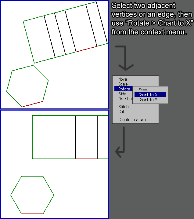
Now, I want you to select some very specific edges, in the 3D window, rotating the object around to whatever angle you need to select them. Follow these screenshots.


Make each side look like this:
Image

Then, select this angle on the top (without de-selecting our previously-selected edges, btw):
Image

Now we have selected enough edges to let Wings know how take our origami sculpture apart and unfold it perfectly! The big secret to this is to make the final resulting edge selections form a LINE (not a circle) of edges, starting at one side of the object and ending at the last face on the other side. This means that we're leaving one face "uncut" to keep everything "together" when we unfold, which results in much better initial maps.

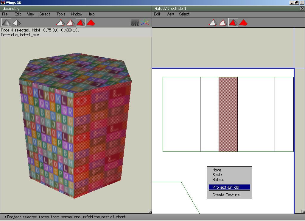
Now, to cut the object, and unfold it, is simplicity itself. Go back to the UV Editor Window, and right-click on one of the selected edges (see how they're red over in this window, just like the 3D view? very handy) and click on Cut.

This will make the lines "jump" a little bit. This is a visual signal that the UI gives us, telling us, "hey, I made a cut in the uvmap". Don't worry, it's OK.

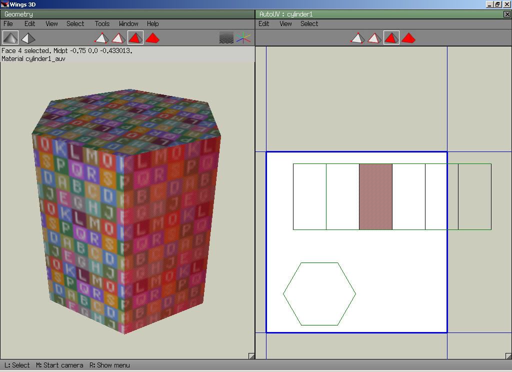
Now it's time to unfold the Object. Select the Object Selection icon, and click on the Object. Then right-click on the Object, and select "Re-Map UV", and left-click on "Unfold".

The result should look like this:

Image

And there you go- you now have unfolded a model efficiently.

"But wait, Argh, what about making a texture with this?"

Easy! In Object Selection mode, just select the object, right-click, and select Create Texture, then tell it what options you want and what size you want it to be :-)

"But wait, Argh, what if my model contains more than one object?"

There are two ways to deal with this issue. One is to cut and unfold every object in the model, and then select ALL of them before exporting from Wings, taking great care not to have any of them overlap each other in the UV Editor Window. That works OK, but it isn't quite as nice as I'd like.

The other way... the "Argh way", if I can be permitted a bit of horn-tooting, is to ignore Wings rather piss-poor handling of things like scale and rotation, and move the now unfolded model over to UVMapper Classic (or, if you're willing to pay for it, Pro, which is much better), and get it sorted out there. That'd be a whole 'nother tutorial, though.

"But wait, Argh, are there any potential problems I should look out for, if I've been making my models in another program?"

Yes! However, the answer to this question gets a bit technical, and I don't have time to break it all down right now.

The veeeeeeery short answer, though, is that:

A. All objects must be completely airtight. Objects with holes will not get handled properly by Wings (which is a real pity, since I like to clip faces as I go, and I will have to un-learn that).

B. Wings does NOT have tools for doing proper NURBs operations, like splits along arbitrary lines, etc. You need to do that stuff before bringing the model in.

C. If you're using Rhino3D, you need to re-weld your geometry so that it is perfectly welded, before bringing it into Wings, or Wings gets confused about whether or not you are importing closed surfaces.
User avatar
rattle
Damned Developer
Posts: 8278
Joined: 01 Jun 2006, 13:15

Post by rattle »

Are we allowed to post some advice to improve the workflow? If not, tell me and I'll edit it out.

"Chart by X/Y" is a neat thing to organize your uvmap fast. It shows up in the context menu when you are in edge mode in the UV window and have an edge selected. "Project Unfold" (from the face context menu) is really useful too when your map is cut properly.
Also I usually scale everything to max. uniform and then scale it down to 25% or 50% (depends on how much detail you need). The move tools are rather poor though cause you can't assign hotkeys to them. Always remember to leave some space between the texture borders and other maps, at least 0.05 WU for borders and 0.1 WU for adjacent maps, on a 512x512 map that is. It's lots of mouse work in comparision to UV mapper but at least I don't break my work so often in wings. :-)

Everyone should assign hotkeys to their most used functions (i.e. Extrude->Normal, Scale->Uniform, Put on etc.). You can do that by highlighting the command in (almost) any menu, then hit insert and then the key to which it should be assigned to. Modifiers like ALT and SHIFT or a combination of both are allowed. It's really a shame you can't assign hotkeys to any of the UV commands though. Also I have no idea how to map the advanced functions to a key yet.

Lastly, make use of the incremental save function. Really helps when things went wrong.
User avatar
diggz2k
Posts: 208
Joined: 04 Mar 2005, 06:34

Post by diggz2k »

Thank you
Warlord Zsinj
Imperial Winter Developer
Posts: 3742
Joined: 24 Aug 2004, 08:59

Post by Warlord Zsinj »

Argh, would you recommend moving over to this program, or sticking with Milkshape/UVmapper classic?
User avatar
Argh
Posts: 10920
Joined: 21 Feb 2005, 03:38

Post by Argh »

@Rattle:

Can you give me a screenshotted example (preferably with the example object, so that newbies grow their foundation from the starter tutorial) to include in the workflow? I am still getting wrapped around the whole "chart" thing.

@Warlord:

I am going to use it for irregular stuff that's a major pain to get mapped any other way (like, say, that walker you made the other day), and to supplement working in UVMapper Pro. Pro does several things far better, imo, but this could be a super-nice way to get a map done fast for things like humanoid figures and odd-angled mechanical greebles.
User avatar
rattle
Damned Developer
Posts: 8278
Joined: 01 Jun 2006, 13:15

Post by rattle »

Um I used a cylinder instead.

Chart to X/Y
Image

Project Unfold
ImageImage
User avatar
Erom
Posts: 1115
Joined: 25 Apr 2006, 05:08

Post by Erom »

Does anyone use Blender for UV mapping? I know it's capable, but I was wondering if anyone had any experience in it being too hard to be worth learning, or useful to learn.

If no one else knows, I suppose I'll try to figure it out come the holidays.

e: thanks for the tute Argh.
User avatar
Snipawolf
Posts: 4357
Joined: 12 Dec 2005, 01:49

Post by Snipawolf »

Another tutorial by one of the "big wigs" in Spring Developing, woohoo!

Thanks Argh (I didn't need it, but I still think it will be helpful for some people :-) )
User avatar
Argh
Posts: 10920
Joined: 21 Feb 2005, 03:38

Post by Argh »

@Rattle:

I can see the immediate benefits of "Chart XY", but what does Project Unfold do? It looks like it's just evening out the projections of the planes on that cylinder- is that what it does?
User avatar
mehere101
Posts: 293
Joined: 15 Mar 2006, 02:38

Post by mehere101 »

@Erom: I use blender all the time for UV mapping. I haven't figured out how to use a lot of the tools they have added in (LCSM and live unwrap etc), but by using some of the included scripts and some ingenuity you can get some pretty good results. BTW, the next blender has texture baking. Much easier to get Ambient Occlusion that way than any other I've found so far...
User avatar
rattle
Damned Developer
Posts: 8278
Joined: 01 Jun 2006, 13:15

Post by rattle »

"Project Unfold" projects the map from the selected face's/(s) normal(s), i.e. if I selected two faces it would use the normal from both (the two faces would be slightly distorted on the uvmap then). It will unfold everything else by projecting the normal as long as the uvmap is cut properly. If it's not then it'll produce garbage. I do a lot of the mapping that way, it's not neccessary though but speeds things up for me that is.
Wings will spew errors by the way if you use that on a coherent map or by having all faces of a map selected.

I'll make some more screenshots showing how to use spherical/cylindrical mapping. Also the auto-smooth function (shows up in the geometry context menu in object mode) will create smooth groups automatically which can be handy sometimes. Reduces the effort of mapping a cylinder to one or two clicks for instance. :-)
Last edited by rattle on 17 Dec 2006, 00:54, edited 1 time in total.
Sheekel
Posts: 1391
Joined: 19 Apr 2005, 19:23

Post by Sheekel »

This is good stuff. Sticky it?
User avatar
aGorm
Posts: 2928
Joined: 12 Jan 2005, 10:25

Post by aGorm »

BTW, hiding a face in wings is teh way it handels holes... I dont know what that means for importing somthing with holes already, but if you want to have a surface with a face or 2 missing you just "hide" the face. Can be done as you UV map to... (PS you may of course have knowen that and be talking about somthing else)

aGorm
User avatar
NOiZE
Balanced Annihilation Developer
Posts: 3984
Joined: 28 Apr 2005, 19:29

Post by NOiZE »

Sheekel wrote:This is good stuff. Sticky it?
someone put it in the wiki IMO
User avatar
Argh
Posts: 10920
Joined: 21 Feb 2005, 03:38

Post by Argh »

I will stick it in the Wiki when it's complete. I'm intending to put a "level 2" project, showing how to make effective use of mirroring and other stuff, but I am solving a rather difficult set of animation scripting problems at the moment :-)
User avatar
rattle
Damned Developer
Posts: 8278
Joined: 01 Jun 2006, 13:15

Post by rattle »

Speaking of mirroring, I made one some time ago for keithus.
http://s111.photobucket.com/albums/n131 ... gs_mirror/
Seperating on a certain axis is really easy.

You'll need an untesselated model for that. Make sure you are in orthographic view (o) and hit y for a top down view on the part (hit a to aim at it). Then go in edge mode and... ah I'll just make some screens and write out steps.

I used the head of your CM as example. :)

http://s111.photobucket.com/albums/n131 ... gs_mirror/

1: Go in (o)rthograhic view Hit Y and aim on the the part to mirror, make sure it's the only thing you see (right click on the eye in the geometry graph does that). Then go in (e)dge selection mode and use the selection band and try to select everything around the center.

2: Move the cam around (in perspective view) and make sure odd edges which can't be split like that are not selected.

3: Hit C to connect them (or use the connect tool).

4: Go in (v)ertex selection mode and now mark all the vertices which are in the center (or almost) and connect them with the rest.

5: Now hit space to deselect everything and use edge selection to select one of the center edges. Then hit L to select all edges in a loop (G does the same just in the other direction) and use Loop cut from the menu or CTRL+SHIFT+L.

6: Then use object selection mode to delete one half. In face selection mode select the large "inner" face and use Flatten -> X. Mark the face again, hit M to mirror it and finally absolute move it in object mode to x = 0.

Done.

It's really easy and can save you a lot of time. I use that method to split complex objects up in halves before uv-mapping them. Actually almost everyone does that, it saves time and makes your models accurate. The flattening part is important because it corrects small modeling mistakes.
Dunno if that's of any use to you.
User avatar
Keithus
Posts: 155
Joined: 06 Oct 2006, 05:59

Post by Keithus »

Oh yea, that was a great little tutorial. Laid out nicely so a noob at modeling like me could pick it up easy. The pictures were especially well laid out for getting my head round the already easy instructions.

Pity that whole tutorial was only viewed by me for so long. Atleast now it out there for the greater good of all :P .
User avatar
AF
AI Developer
Posts: 20687
Joined: 14 Sep 2004, 11:32

Post by AF »

Would you mind if I put up a copy at darkstars so it doesnt get lost?

And is there anything you'd like to change in it considering the replies after the first post?
User avatar
Maelstrom
Posts: 1950
Joined: 23 Jul 2005, 14:52

Post by Maelstrom »

Could you also mention about welding and how it relates to the UV map? Cause untill you mentiond that welding is applied via splits/join in the UV map, I had no idea.

Also, you can make the whole join/split thing easier by setting hard/soft edges in the main window. Then, when UV mapping, hard edges will be 'Marked for cut', basically setting up all the welding like you had in the main geometery window (I think).
User avatar
Argh
Posts: 10920
Joined: 21 Feb 2005, 03:38

Post by Argh »

Yes, by all means, put it whereever you want. I want to include Rattle's information and a link to that other tutorial, as well as writing up a "advanced" version to help people get to the next level, and tackle some closer-to-real-world problems with this :-)

And yeah, I should probably talk about welding issues, although tbh Wings doesn't seem to be a good environment to get really good control over this- I really prefer doing it with UVMapper.
Post Reply

Return to “Art & Modelling”